cnc box joint jig…the beginning
2015-05-17 written by: Brad
I’ve recently been playing around with the Raspberry Pi and after spending a little time lighting up LED’s and setting up thermistors and voltage monitoring circuits I decided to try and tackle a CNC
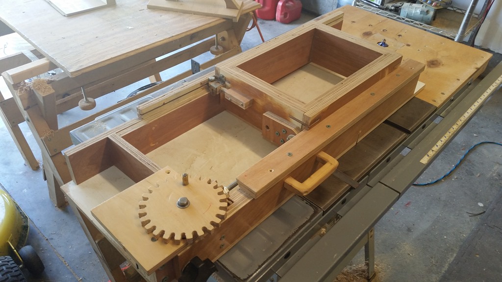
A few years ago I built Mathias Wandell’s box joint jig. The great part about his design is it is almost ready to just mount the stepper motor and start cutting. I am sure there will be some mods necessary to fit every thing together, but that is all part of the fun. If you haven’t seen it you should go check it out, he has plans available for those that want to purchase and build one like it.
I started this endeavor using a small salvaged stepper motor from a printer to figure out and write most of the python code I am using for the CNC machine. I ended up tearing apart two laser printers I found at a Habitat for Humanity store for the affordable price of 5 bucks a piece. I ended up with a nice collection of stuff to play around with in the future, but for this project the main part I used was the power supply. It is a switching supply that provides multiple voltages…of course I am only using the 24v output.
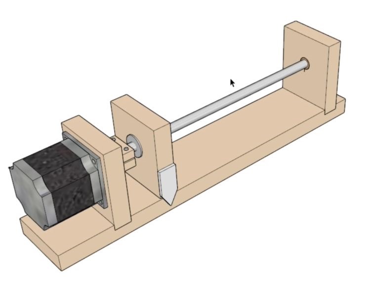
I figured it would be best to build a quick and easy test jig so I could get some accurate measurements with my calipers and fine tune the code so I drew up a simple and easy to build jig that I can mount a NEMA 23 stepper motor to.
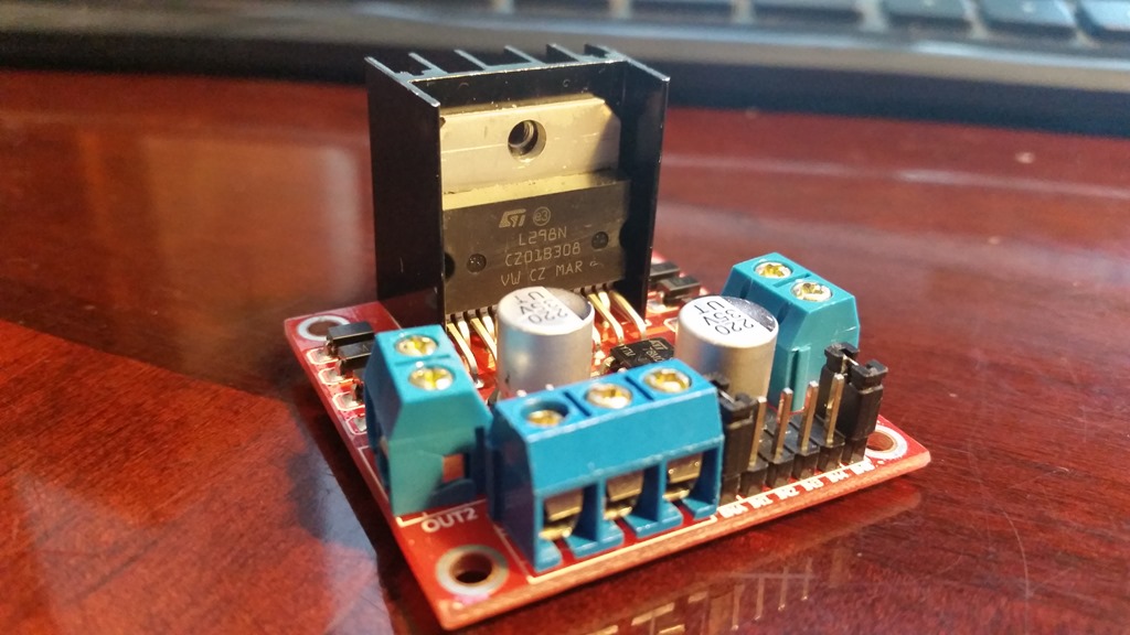
While I was testing with the jig I managed to burn up two cheap motor controllers so I went on the hunt for a suitable replacement and ran across a nice circuit drawn up over at mycontraption.com. I decided it would be fun to build my own motor controller too. A link here to that site.
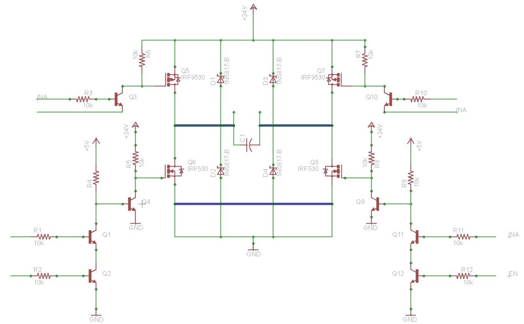
He provided the circuit drawn up in a program called Eagle. It is a nice program for drawing schematics and PCB layout. I ended up downloading the program and redrawing the circuit so I could lay it out on the small circuit boards I purchased earlier to play around with.

The Eagle software allowed me to layout the components on my small through hole circuit board and route the jumpers so they wouldn’t be piled up too bad. I was able to fold over the leads of the components to make a good portion of the connections underneath the board.
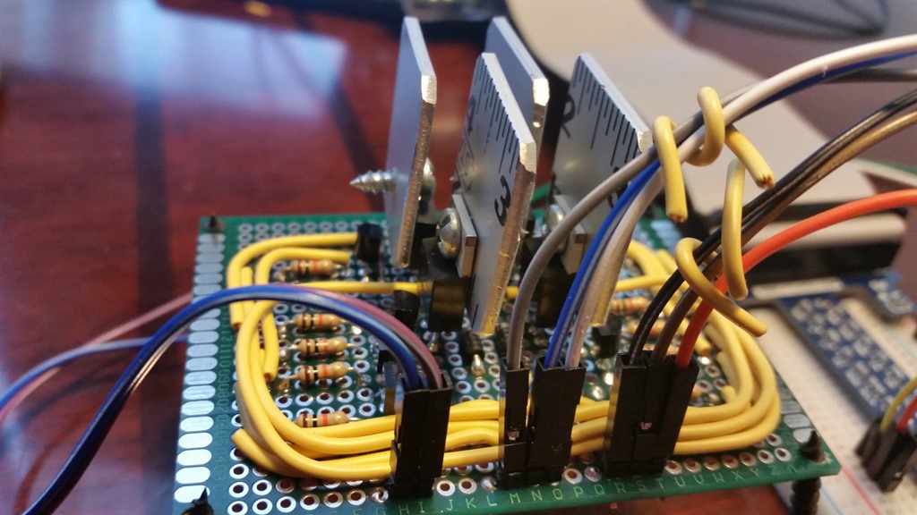
Now I am finally to the point where I have the stepper motor hooked up to my test jig and my homemade motor controllers seem to be handling the motor just fine…although I did have to put some heat sinks on the power transistors. It seems to be doing okay with the make-shift heat sinks (cut from an aluminum ruler )
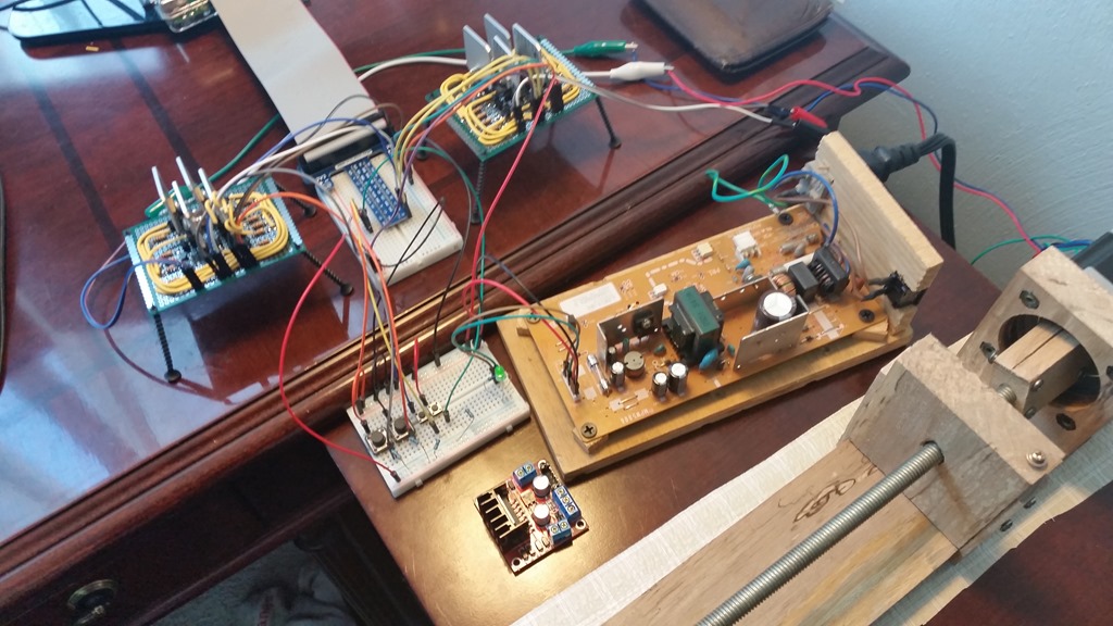
In the near future I will be mounting the stepper motor onto my box joint jig for further testing. I am not sure at this point if it has enough power to be directly coupled to the 3/8 drive rod…we shall see.
Category: Miscellaneous Projects